The structural analysis software RFEM 6 is the basis of a modular software system. The main program RFEM 6 is used to define structures, materials, and loads of planar and spatial structural systems consisting of plates, walls, shells, and members. The program also allows you to create combined structures as well as to model solid and contact elements.
RSTAB 9 is a powerful analysis and design software for 3D beam, frame, or truss structure calculations, reflecting the current state of the art and helping structural engineers meet requirements in modern civil engineering.
Do you often spend too long calculating cross-sections? Dlubal Software and the RSECTION stand-alone program facilitate your work by determining section properties of various cross-sections and performing a subsequent stress analysis.
Do you always know where the wind is blowing from? From the direction of innovation, of course! With RWIND 2, you have a program at your side that uses a digital wind tunnel for the numerical simulation of wind flows. The program simulates these flows around any building geometry and determines the wind loads on the surfaces.
Are you looking for an overview of snow load zones, wind zones, and seismic zones? Then you are in the right place. Use the Geo-Zone Tool to determine quickly and efficiently snow loads, wind speeds, and seismic data according to ASCE 7‑16 and other international standards.
Would you like to try out the capabilities of the Dlubal Software programs? You have the opportunity to do so! The free 90-day full version allows you to thoroughly test all our programs.
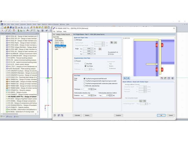
The RF‑/FRAME‑JOINT Pro add-on module designs rigid bolt connections between columns and horizontal beams, and classifies these connections. The rigid bolt connections are designed with the ultimate load method according to Eurocode 3 or DIN 18800.
The dimensions of an end plate can be defined in the add-on module. Bolts are possible in the extensions; however, only in the extension at the top.
A bolt row in the bottom extension is not intended, which is the reason the error message appears.
You can check the minimum dimension under the design hints in the add-on module.
The desired geometry can be entered in the RF‑/JOINTS Steel - Rigid add-on module.
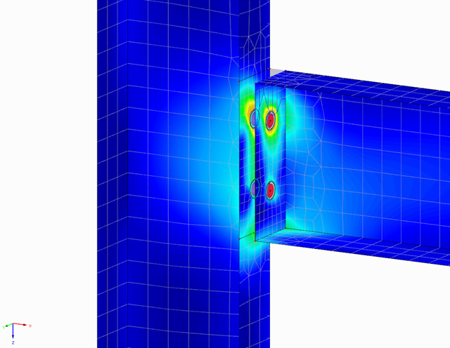
In RF-JOINTS, an idealized design of a steel connection according to the standard is performed, which cannot be compared easily to an exact FE calculation. The results of the numerical and analytical design methods differ in particular due to the simplifications and assumptions made.
For example, the following points must be considered when calculating a joint as a surface model:
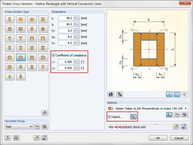
In timber design, beams are often built up of several timber elements. The individual elements can be connected with glue, nails, bolts, or dowels. A glued connection is to be assumed as rigid. In the case of dowel‑type fasteners, the joint is compliant (slip joint), and the cross‑section properties of the connected elements cannot be fully applied.
In RFEM and RSTAB, it is possible to consider the compliance (slip) of the connection in the individual layers. This can be done by specifying the coefficient of compliance gamma, which can be determined by means of the gamma method, for example according to EN 1995‑1‑1 (Annex B). By using this coefficient, the Steiner components of the cross-section parts are reduced, resulting in an effective bending stiffness.
In addition, it is possible to assign different materials to the individual cross‑section. To do this, use the "Hybrid" function, in which one of these materials is used as reference for the determination of the ideal cross-section properties.